The star and delta connections are two common types of connections used in the winding of three-phase motor. For star connection or delta connection of winding, six wires or leads of the motor winding must be accessible.
3-phase motors are commonly used in industrial applications due to their efficiency and power output. They operate using three separate phases of electrical power, creating a rotating magnetic field that drives the motor’s rotor. This design allows for smoother operation and higher torque compared to single-phase motors.
In a 3-phase system, each phase is displaced by 120 degrees from the others, creating a balanced power supply that ensures even distribution of power throughout the motor. This balanced power supply is crucial for maintaining the motor’s performance and efficiency.
In the star connection, also known as the Y connection, the three ends of the motor winding are connected together to form a common neutral point. This connection results in a lower line voltage compared to the delta connection. The star connection is often used when the motor needs to operate at a lower voltage.
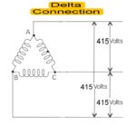
the delta connection, also known as the Δ connection, does not have a common neutral point. Instead, the ends of the motor winding are connected in a triangular shape. This connection results in a higher line voltage compared to the star connection. The delta connection is often used when the motor needs to operate at a higher voltage.
The choice between the star and delta connections depends on the specific requirements of the motor and the application. Factors such as the available voltage and the desired motor performance need to be considered when deciding on the appropriate connection.
It is important to note that the star and delta connections affect the motor’s torque-speed characteristics.
When connecting a three-phase motor in a star or delta, it is crucial to follow the correct wiring diagrams.
Star Connection Of 3 Phase Motor Winding
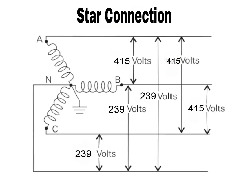
- Three phase Induction motor has three winding each winding has two ends labeled as U1 and U2 , V1 and V2 ,W1 and W2
- Star connected induction motor depicted in below diagram.
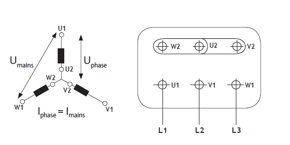
- Begin by identifying the three terminals of the motor labeled U1, V1, and W1. These are the main power terminals for the motor.
- Connect terminal U1 to one end of one phase of the power supply using a wire.
- Connect terminal V1 to one end of another phase of the power supply using a wire.
- Connect terminal W1 to one end of the third phase of the power supply using a wire.
- Once all three terminals are connected to their respective phases, connect other three loose ends U2 ,V2 and W2 together at a central point known as the neutral point. As shown in the above connection Diagram.
- Ensure that all connections are secure and tight to prevent any loose connections during operation.
- Check that there are no loose wires or exposed connections that could cause short circuits or electrical hazards.
- By following these steps carefully and ensuring each connection is secure, you can successfully connect a 3-phase motor in star configuration for optimal performance and efficiency.
Delta Connection Of 3 Phase Motor Winding
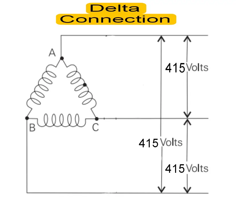
Connecting a 3-phase motor in delta configuration involves a specific wiring arrangement that allows the motor to operate efficiently. The below diagram shows delta connected 3 phase induction motor.
To do this, follow these steps:
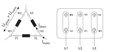
- Begin by identifying the six terminals of the motor – U1, V1, W1 and U2 V2 and W2
- Connect terminal U1 to W2 through a wire, creating one phase of the delta configuration.
- Connect terminal V1 to U2 through another wire, forming the second phase of the delta setup.
- Finally, connect terminal W1 back to V2 with a third wire, completing the delta connection. As depicted in the above wiring diagram
- Ensure that all connections are secure and tight to prevent any loose wires during operation.
- Double-check your wiring diagram or consult an electrician if you are unsure about any step in the process.
- Once all connections are made correctly, you can power up the motor and test its functionality in the delta configuration.
By following these steps carefully and paying attention to detail, you can successfully connect your 3-phase motor in a delta configuration for optimal performance.
Keep up the amazing work!