Transformers play an important role in electrical power distribution and transmission systems, as they facilitate step-up and step-down voltage for distribution and transmission purposes. Because of its electricity to be transmitted efficiently. To protect transformers, various devices are fitted on the tank to ensure safe and reliable operation. One of them is the Pressure Relief Valve (PRV) also called the pressure relief device(PRD). In this article, we will explore what is PRV In Transformer their Construction, and their working principle.
Table of Contents
PRD is shown in the below diagram
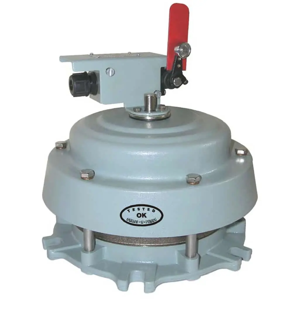
What is a Pressure Relief Valve (PRV)?
A Pressure Relief Valve (PRV) is a safety device installed on the transformer tank to protect them from excessive internal pressure buildup during an electrical fault in winding.
Transformers generate heat due to internal winding faults and overload. which can cause the internal temperature of oil and pressure to rise and heating of transformer oil generates enormous gases inside the transformer tank which rise pressure within the tank. If this pressure exceeds safe limits, it can lead to transformer failure, explosion of the tank, equipment damage, or even pose a safety risk. The PRV ensures that excessive pressure is released, preventing such incidents.
Construction of PRV in Transformer
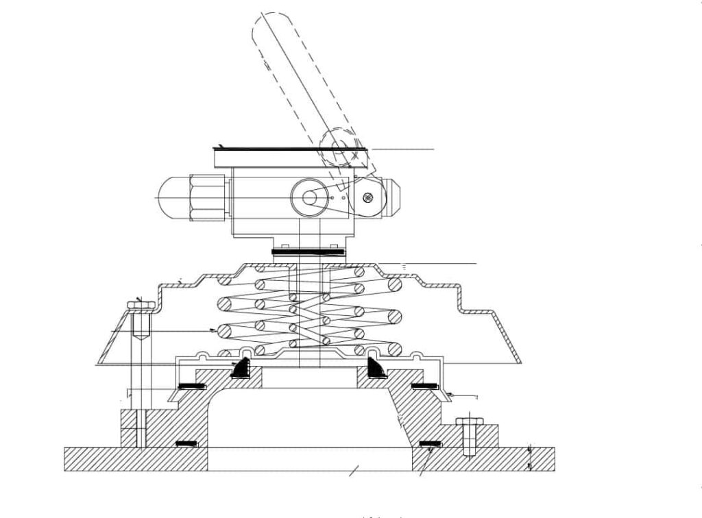
The Pressure Relief Valve (PRV) is a spring-loaded valve having a unique arrangement for instantaneous pressure release during a fault in the transformer. The above Diagram shows a cut view of PRV.
The PRV unit is mounted on a transformer tank. The stainless steel Diaphragm is kept pressed by two heavy-duty reverse wound Springs and seals the port preventing it from opening during normal operation. The pressure die-cast aluminum cover retains and compresses heavy-duty springs.
PRD also has a Flag for indication, which is operated by a Switch Operating Rod. The Switch Assembly has one NO and one NC contact for tripping of breaker and giving the alarm. Movement of Flag indicates actuation of PRV.
The operating pressure setting of PRV/PRD of the transformer is ranging from 0.42 Kg/cm² to 0.70 Kg/cm².
Port Opening: T3 – 70 mm, T6 – 150 mm
Working Principles of PRV in Electrical Transformer
The working of PRVs in transformers is based on their ability to regulate internal pressure. Let’s understand the working principles
Normal Operation of Transformer: During normal operation, the pressure spring applies force to keep the valve port closed. The valve Diaphragm remains seated on the valve port, maintaining a sealed system.
Pressure Buildup: As the fault or overloading condition developed inside the transformer tank, heat is generated, causing the internal temperature and pressure to rise drastically. If the developed pressure exceeds a safe limit, it can lead to equipment damage or pose safety risks.
Pressure Relief: When the internal pressure exceeds the predetermined threshold limit, the pressure spring which compressed, overcoming its force Internal pressure lifts the valve Diaphragm off the valve port, creating an escape path for excess pressure.
Safe Pressure Release: As the valve opens, the excess pressure is safely released through vents in the PRV housing. This prevents pressure buildup from reaching dangerous levels, safeguarding the transformer.
Resetting and Re-engagement: Once the pressure is vented in the atmosphere and returns to a safe range, the pressure spring pushes the valve Diaphragm back onto the valve port, closing the PRV. The transformer can then resume normal operation
Conclusion:
Pressure Relief Valves (PRVs) are essential safety devices in electrical transformers. Their construction and working principles enable the controlled release of excessive internal pressure, preventing equipment damage and ensuring safe operation. By understanding the importance of PRVs and their role in safeguarding transformers, we can appreciate their contribution to maintaining reliable and efficient power distribution systems.