Function and Principles of Synchroscope Synchronizing
Synchronizing generators is a critical process in power systems, ensuring that multiple generators or a generator and the grid operate in harmony. Proper synchronization prevents mechanical stress, electrical transients, and potential damage to equipment. One of the key tools used in this process is the synchroscope. This article provides a detailed explanation of the synchroscope, its working principle, and the steps involved in synchronizing generators using this device.
Table of Contents
What is a Synchroscope?
A synchroscope is an instrument used to indicate the phase difference and frequency difference between two alternating current (AC) power sources. It is primarily employed to synchronize an incoming generator (or alternator) with an existing power system or another generator before connecting them in parallel.
The synchroscope provides a visual indication of whether the generator is running faster or slower than the system and whether the phase angles are aligned. This information is crucial for ensuring that the generator is synchronized correctly before closing the circuit breaker.
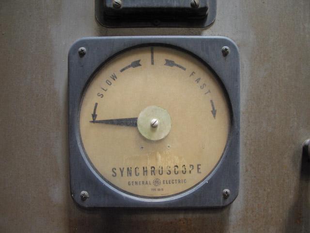
The device typically features a dial with a rotating pointer, indicating whether the frequency of an incoming generator is faster or slower compared to the busbar.
Synchronization is important to prevent damaging surges in power systems by aligning voltage, frequency, and phase angle.
The incoming generator must have:
- A voltage magnitude equal to the busbar
- Be in phase with the busbar
- Operate at the same frequency as the busbar
Operating Methods
The synchroscope’s pointer rotation direction reveals the frequency relationship between the incoming generator and the busbar:
- Clockwise rotation: Generator frequency exceeds grid frequency – decelerate prime mover
- Anticlockwise rotation: Generator frequency lags grid frequency – accelerate prime mover
- Stable pointer: Ideal moment for synchronization
Analog synchroscopes use mechanical dials where the pointer’s rotation provides a direct indication of frequency variances.
Digital synchroscopes offer numerical readings of frequency and phase difference on a digital display, often eliminating the need for auxiliary information displays.
Supplementary instruments, such as phase sequence indicators, remain essential to ensure safe and seamless synchronization, particularly in multi-phase systems.
Synchroscope Synchronizing Process
The Synchroscope synchronizing process involves several key steps:
- Phase sequence alignment: The incoming alternator’s phase sequence must match the busbar’s sequence.
- Voltage matching: The incoming alternator’s voltage is adjusted to match the busbar’s.
- Frequency tuning: The incoming alternator’s frequency is finely tuned to match the busbar’s. The synchroscope displays frequency differences in real-time, allowing engineers to adjust the prime mover’s throttle for alignment.
- Zero-phase point achievement: The synchroscope guides the final step, indicating when both power systems are in unison and ready for the circuit breaker to close the connection.
Throughout this process, supplementary tools like phase sequence indicators ensure thorough verification of each aspect of synchronization, safeguarding the overall integrity of the power system.
Applications of Synchroscope Synchronisation
Synchroscopes are essential in various power systems, from industrial complexes to utility grids. In industrial setups with multiple generators, they enable smooth integration of additional generating units without causing disruptions. This is particularly important when facilities increase production capacity and require more power.
In utility grids, synchroscopes help connect various power stations to grid, maintaining a continuous, balanced flow of electricity. Their proper use can prevent cascading failures that lead to widespread outages.
“Unsynchronized attachments of generators can lead to mechanical stress on rotating machinery, resulting in costly repairs and hazardous working conditions.”
Analogue vs Digital Synchroscopes
| Analogue Synchroscopes | Digital Synchroscopes |
| Operate with mechanical dials and rotating pointers | Leverage advanced electronics |
| Offer visual clarity and reliability | Provide precise numerical data |
| Preferred in environments favoring direct mechanical feedback | Present real-time readouts of frequency and phase differences |
| Excel in reliability and ease of use | Offer comprehensive evaluation suited to modern, fast-evolving power networks |
The choice between analogue and digital synchroscopes depends on specific installation requirements, operational environment, system complexity, and user proficiency. Recent advancements in digital models include touchscreen interfaces and enhanced graphical displays, which emulate traditional dials while incorporating additional data layers.
Synchroscope image credit wikipedia.