Star delta starter is a very common type of starter and usually use to start a three-phase induction motor. Star delta starter also called a Y-delta starter is used for squirrel cage motors that are designed to run normally on delta-connected stator winding. In this article, we are going to see the star delta starter working principle, control wiring diagram, and power circuit.
Different starters are used to start induction motors because the electrical motor draws a very large current at starting like
DOL Motor starter, Autotransformer stater, and Soft starter.
Star Delta starter is a reduced voltage starter which means it reduces the voltage at starting and when the motor attains sufficient speed say 80% then it applies full line voltage to the motor.
Wye-Delta starter is useful where all six terminals of the motor are accessible.
Star delta starter is the simplest starter which use to reduce the inrush starting current of the Induction motor.
The limiting high starting inrush current causes a reduction of starting torque of the motor. Hence it is suitable for loads that are not loaded until after the start.
Star Delta Starter Working Principle.
At starting of the motor the stator winding is connected in a star, when the motor picks up the speed say 80% of its rated full speed. the delta contactor is switched on and the star contactor is switched off, during starting the main contactor and star contactor remain energized.
At a normal run, the main and delta contactor remains ON. This switching of contactors is done with the help of a timer as shown in the control diagram of the star-delta starter.
By connecting the stator winding in the star at first and then in the delta, the line current drawn by the motor at starting is reduced to 1/3 as compared to starting current with the windings connected in the delta.
At starting torque developed in an induction motor is proportional to the square of applied voltage. star delta starting reduced starting torque to 1/3 that of direct starting.
Star delta starter work in three state
Star state:
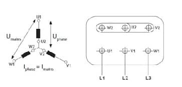
Current=Iphase=I line
Voltage =Vphase =VLine/√3
During starting time of the star delta starter, the star contactor and main contactor remain latched and the motor gets connected in the star state. In star connected state voltage applied across the motor winding is reduced to 1/√3 times of line voltage.
Open state:
Between switching from star to delta, the stator circuit becomes open and the motor neither remains in the star nor in the delta state this state is called an open transition state.
Delta state:
For the normal run, the motor connected in the delta state after activation of the timer star contactor gets de-energized and the delta contactor becomes ON and the motor starts running in the delta state.
In delta connection Vphase =V line
Hence full line voltage is applied to the motor winding and three phase induction motor run at rated full speed, delta connected motor winding is shown in the diagram.
Star Delta Starter Control Diagram
 |
| Star delta control diagram |
Star Delta starter control circuit diagram consists of a timer, and push-button, for start and stop.
At starting when we press the start push button single phase supply activates the timer, And it energized the star contactor as the NC of the timer is in series with the star contactor coil as shown in the control wiring diagram. After some time, the timer gets activated and it opens the star contactor and closes the delta contactor, as its coil is in series with timer NO contact.
Star Delta Starter Power Circuit Wiring Diagram
The Star Delta starter power circuit diagram is shown below figure.
 |
| Star delta starter power circuit diagram |
Where,
KM1 – Star Contactor
KM2- Delta Contactor
KM3- Main Contactor
OLR- Overload Relay
M- Induction Motor
Initially during starting time of the motor KM1(Star contactor) and KM3(Main Contactor) remain energized and after attaining sufficient speed KM2 (Delta contactor) and KM3 remain ON hence motor is connected in the delta.
Star contactor is taking part in the circuit only during starting time and carries star current only
Components of Star Delta Starter
Overload relay (OLR)
Electric motors need overcurrent protection to prevent damage from over-loading the motor, or to protect against short circuits in connecting cables or internal faults in the motor windings. hence overload relay is used in the star delta starter circuit. The rating of the overload relay is 0.58 X full load current.The overload sensing devices are a form of the heat-operated relay where a coil heats a bimetallic strip, or where a solder pot melts, releasing a spring to operate auxiliary contacts.
These auxiliary contacts are in series with the coil. If the overload senses excess current in the load, the coil is de-energized.
This thermal protection operates relatively slowly allowing the motor to draw higher starting currents before the protection relay will trip. Where the overload relay is exposed to the same environment as the motor, a useful though crude compensation for motor ambient temperature is provided.
The other common overload protection system uses an electromagnet coil in series with the motor circuit that directly operates contacts. This is similar to a control relay but requires a rather high fault current to operate the contacts.To prevent short over-current spikes from causing a nuisance triggering the armature movement is damped with a dashpot. The thermal and magnetic overload detections are typically used together in a motor protection relay.
Electronic overload protection relays measure motor current and can estimate motor winding temperature using a “thermal model” of the motor armature system that can be set to provide more accurate motor protection.Some motor protection relays include temperature detector inputs for direct measurement from a thermocouple or resistance thermometer sensor embedded in the winding.
Contactor
In star delta starter 3 contactors are used. Main contactor, star contactor, and delta contactor.
A contactor is a heavy-duty relay with higher current ratings, used for switching electric motors and lighting loads. Continuous current ratings for common contactors range from 10 amps to several hundred amps.
Contactors can be noisy when they operate (switch on or off), so they may be unfit for use where noise is a chief concern. In such cases, solid-state relays are preferred.
Contactor Selection in Star Delta starter
Rating of Main and Delta Contactor:
Rating of Main and Delta contactor= Full Load current X 0.58
Size of Star contactor:
At starting KM1 (star contactor) and KM3 (main contactor) remain closed and star contactor carries star current only during starting. the current in the star is 1/3 of the delta current.
Hence the rating of Star contactor: Full Load current X 0.33
Timer
The timer is used in the star-delta starter to switch the motor from star to delta after gaining 80% of the rated speed. Timers NO and NC contacts are used to switch starter from wye to delta state.
Stop button NC (normally closed type)
Stop push button used in Wye delta starter circuit is NC type and used to stop the motor
Start button NO (normally open type)
The start button is normally open type and used to start motor
Advantages of Star Delta Starter
- Star-Delta starters are popular due to their low price.
- There are no limits to the number of times they can be operated.
- The starting current is reduced to approximately 1/3 of the rated motor current.
Disadvantages
- Star delta starter can only use to motors where the six terminals can be accessed.
- The supply voltage must be the same as the rated motor voltage for the Delta connection.
- Due to starting current reduced 1/3 of the rated current, the torque also reduced to 1/3 during starting.